|
|
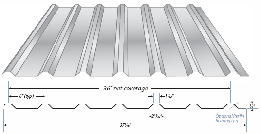
"U" Panel Information
"U" PANEL
ALLOWABLE LOAD (PSD)* |
| |
|
SPAN
IN FEET |
| SPAN TYPE |
LOAD TYPE |
1.5' |
2' |
2.5' |
3' |
3.5' |
4' |
4.5' |
5' |
5.5' |
6' |
6.5' |
7' |
7.5' |
8' |
8.5' |
9' |
| Single |
Positive Wind |
386 |
217 |
139 |
96 |
70 |
54 |
42 |
34 |
28 |
24 |
20 |
17 |
15 |
13 |
12 |
10 |
| Negative Wind |
329 |
185 |
118 |
82 |
60 |
46 |
36 |
29 |
24 |
20 |
17 |
15 |
13 |
11 |
10 |
9 |
| Live |
386 |
217 |
139 |
96 |
70 |
54 |
42 |
34 |
28 |
24 |
20 |
17 |
15 |
13 |
12 |
10 |
| Deflection (L/180) |
492 |
207 |
106 |
61 |
38 |
25 |
18 |
13 |
9 |
7 |
6 |
4 |
3 |
3 |
2 |
2 |
| Deflection (L/240) |
369 |
155 |
79 |
46 |
29 |
19 |
13 |
9 |
7 |
5 |
4 |
3 |
2 |
2 |
2 |
1 |
| 2 Span |
Positive Wind |
315 |
180 |
116 |
81 |
60 |
46 |
36 |
29 |
24 |
20 |
17 |
15 |
13 |
11 |
10 |
9 |
| Negative Wind |
364 |
210 |
136 |
95 |
70 |
53 |
42 |
34 |
28 |
24 |
20 |
17 |
15 |
13 |
12 |
10 |
| Live |
315 |
180 |
116 |
81 |
60 |
46 |
36 |
29 |
24 |
20 |
17 |
15 |
13 |
11 |
10 |
9 |
| Deflection (L/180) |
998 |
421 |
215 |
124 |
78 |
52 |
36 |
26 |
20 |
15 |
12 |
9 |
7 |
6 |
5 |
4 |
| Deflection (L/240) |
748 |
315 |
161 |
93 |
58 |
39 |
27 |
20 |
15 |
11 |
9 |
7 |
5 |
4 |
4 |
3 |
| 3 Span |
Positive Wind |
387 |
223 |
144 |
101 |
74 |
57 |
45 |
36 |
30 |
25 |
21 |
18 |
16 |
14 |
12 |
11 |
| Negative Wind |
444 |
258 |
168 |
118 |
87 |
67 |
53 |
43 |
35 |
30 |
25 |
22 |
19 |
16 |
15 |
13 |
| Live |
387 |
223 |
144 |
101 |
74 |
57 |
45 |
36 |
30 |
25 |
21 |
18 |
16 |
14 |
12 |
11 |
| Deflection (L/180) |
781 |
329 |
168 |
97 |
61 |
41 |
28 |
21 |
15 |
12 |
9 |
7 |
6 |
5 |
4 |
3 |
| Deflection (L/240) |
586 |
247 |
126 |
73 |
46 |
30 |
21 |
15 |
11 |
9 |
7 |
5 |
4 |
3 |
3 |
2 |
| 4 Span |
Positive Wind |
363 |
209 |
135 |
94 |
69 |
53 |
42 |
34 |
28 |
23 |
20 |
17 |
15 |
13 |
11 |
10 |
| Negative Wind |
418 |
242 |
157 |
110 |
81 |
62 |
49 |
40 |
33 |
28 |
23 |
20 |
17 |
15 |
14 |
12 |
| Live |
363 |
209 |
135 |
94 |
69 |
53 |
42 |
34 |
28 |
23 |
20 |
17 |
15 |
13 |
11 |
10 |
| Deflection (L/180) |
830 |
350 |
179 |
103 |
65 |
43 |
30 |
22 |
16 |
12 |
10 |
8 |
6 |
5 |
4 |
3 |
| Deflection (L/240) |
622 |
262 |
134 |
77 |
49 |
32 |
23 |
16 |
12 |
9 |
7 |
6 |
4 |
4 |
3 |
2 |
NOTES:
- Allowable uniform loads are based
upon equal span lengths.
- Positive Wind is wind pressure
and is not increased by 33 1/3%.
- Negative Wind is wind
suction or uplift and is not increased by 33 1/3%.
- Live is the allowable live or snow load.
- Deflection
(L/180) is the allowable load that limits the panels
deflection to L/180.
- Deflection (L/240) is the allowable
load that limits the panels
deflection to L/240.
- The weight of the panel has not
been deducted from the
allowable loads.
- Positive Wind, Negative Wind, and
Live Load values are limited
to combined shear & bending using Eq. C3.3.1-1
of the AISI
Specification.
- Positive Wind and Live Load values are
limited by web
crippling using a bearing length of 2".
- Web crippling
values are determined using a ratio of the uniform
load actually supported by the top flanges of the section.
- Section properties are
calculated in accordance
with the 2001 AISI North
American Specification for
the Design of Cold-Formed
Steel Structural Members.
- Ix is for deflection
determination.
- Se is for bending.
- Ma is the allowable bending moment.
- All values are
for one foot of panel width.
*Oil canning is a natural
occurance in metal and is
not cause for panel rejection.
"U" PANEL
SECTION PROPERTIES |
| |
TOP
IN COMPRESSION |
BOTTOM
IN COMPRESSION |
Panel Guage |
Weight
PSF |
KY
KSI |
lx
IN.4 |
Se
IN.3 |
Ma
KIP IN. |
lx
IN.4 |
Se
IN.3 |
Ma
KIP IN. |
26 |
0.87 |
80 |
.0190 |
.0353 |
1.3043 |
.0130 |
.0130 |
1.1130 |
|